 Camera with port enlarged |
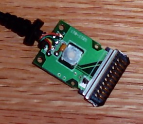
 Palm connector, naked, top |
 Palm connector, naked, bottom, with wire and cut See un-cluttered version |
 Palm connector pin numbering |
By Tyler Bletsch (email: tkbletsc (AT) operamail.com)
14 November 2003
These directions assume a knowledge of T. R. Gipson's original article on interfacing with the camera. In addition, you'll need the following resources:
There are three things stopping you from hooking that palm cable right into the camera and using it immediately:
The first problem is probably the hardest: the opening must be expanded by melting/shaving the plastic. The second problem is solved by soldering to the PCB inside the Palm connector itself. The final problem is remedied by simply splicing the Palm cable to the USB cable.
| |
| |
| |
|
The pinout requires only pins 6, 8, 9, and 10. The connector only implements pins 1, 5, 6, 7, 8, and 10. Hence, pin 9 on the connector is unconnected, while pin 5 (among others) is unneeded. We will take advantage of this by using pin 5's line for pin 9, and disconnecting pin 5.
Pin 5 is now shorted to pin 9. This is undesired and could have unpredictable (and possibly damaging) results.
Note that there is a button on the connector that appears to bridge a capacitor between two of the lines. As this is obviously not the intent, I left the plastic button-cap out to prevent it from being pushed. You may wish to pursue a more elegant alternative.
If the USB cable is standard, then the USB color codes in the table apply. If the serial cable is the same as mine internally, and you chose pin 5 to be the replacement for pin 9, then the "Palm color" column of the table is also applicable. The pinout is as follows:
| Palm pin number | Palm color (if same as mine) | USB line | USB color (if standard) |
|---|---|---|---|
| 10 | Orange | Ground | Black |
| 9 (formerly 5) | Yellow | Data - | White |
| 8 | Brown | Data + | Green |
| 6 | Black | +5VDC | Red |
With a little stabbing with a soldering iron and some defunct cables, one can have an inexpensive fair-quality digital camera. Best of all, because it's cheap and easily modifiable, it is great for high-risk experiments, automatically triggered snapshops (with a little help from an Atmel AVR), etc. Horrah!
My price point for a digital camera was less than $20, so I was waiting for the day when the digital cameras would become affordable to the impoverished student. I read T. R. Gipson's article one day on interfacing with the Dakota single-use camera. I was so enamored with the concept that I bought the camera the next day. I happened to have the a Palm serial connector cable from a defunct Palm M100 (mentioned in the article). I decided to try to use the Palm connector, as my soldering abilities are quite feeble. End result: it works great. Hence, I thought I'd share my procedure for using the Palm connector.